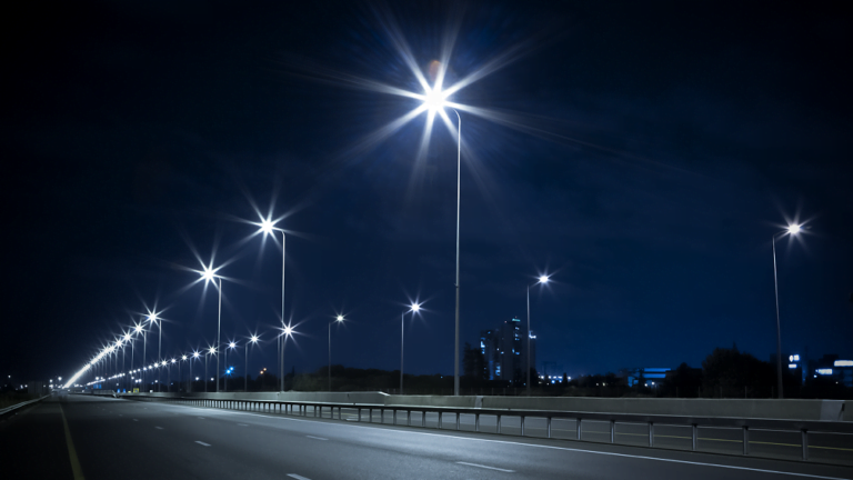
The use of modern LED luminaires in road lighting allows for significant energy savings and can be an opportunity to improve lighting conditions on illuminated road sections. Therefore, cities, municipalities and road managers decide to invest in modern lighting solutions.
Optimal use of the advantages of the new LED technology and ensuring proper quality of lighting will be guaranteed by appropriate project brief, proper lighting design and installation as well as, which is equally important, tools to verify the compliance of the investment with the design and assumptions.
Text by Krzysztof Wandachowicz, M.Sc., Ph.D., D.Sc., Małgorzata Zalesińska, M.Sc., Ph.D. at Poznań University of Technology, Jacek Dylak, M.Sc., Mikołaj Przybyła, M.Sc.
Practice shows that a lot of effort is made on preparing tender specifications, which are to guarantee the investor the highest quality equipment to be delivered in the investment process. However, the question whether the assumptions and the project were correct arises. Moreover, the issue of whether there were any changes affecting the lighting performance parameters implemented at the execution stage emerges. And finally, the verification of the luminaries’ correspondence to the specification comes up.
One of the methods described in the current EN 13201 standard is to measure the distribution of luminance produced on the road. This article will present guidelines for the design of road lighting, methods and instruments of measurement as well as experiences and problems related to the performance of measurements in road lighting.
What kind of roads are illuminated and how is the quality of the road lighting verified?
The European standard EN 13201 Road Lighting provides the basis for the design and assessment of road lighting parameters. In 2014, Technical Committee 169 “Light and Lighting” (CEN/TC169) of the European Commission for Standardization published the first part of the new version of the existing standard – Technical Report, containing guidelines and procedures for the selection of lighting requirements. At the end of 2015, the remaining parts of the updated version of the standard were published, including the latest – the fifth one, concerning the assessment of energy performance of road lighting installations.
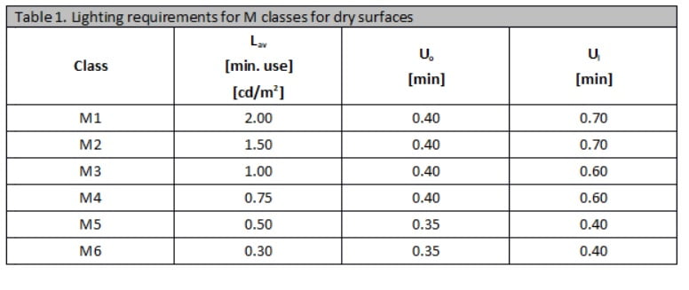
| Klasse | Lmitt [min. Einsatz] [cd/m] | Uo [min] | Ul [min] |
|---|---|---|---|
| M1 | 2,00 | 0,40 | 0,70 |
| M2 | 1,50 | 0,40 | 0,70 |
| M3 | 1,00 | 0,40 | 0,60 |
| M4 | 0,75 | 0,40 | 0,60 |
| M5 | 0,50 | 0,35 | 0,40 |
| M6 | 0,30 | 0,35 | 0,40 |
Tabelle 1: Beleuchtungsanforderungen für M-Klassen bei trockenen Oberflächen.
The general assumptions concerning both the selection procedures and the quantitative lighting requirements in the new standard are based on the publication of the International Lighting Commission of 2010 entitled “Lighting of roads for motor traffic and pedestrians”.

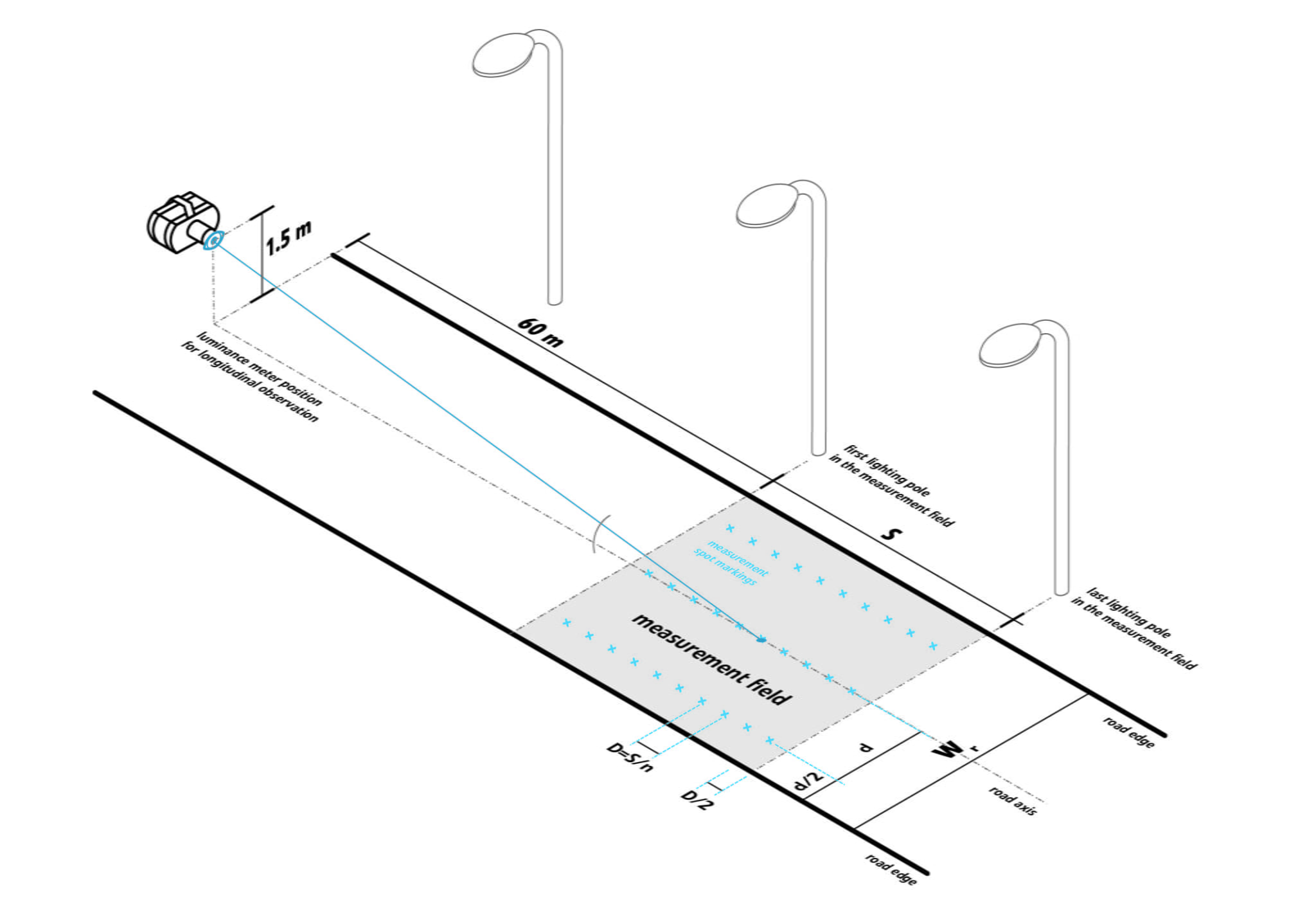
Abbildung 1: Berechnungsfeld der Leuchtdichte: Positionen der Berechnungspunkte in der Fahrspur: Rand der Fahrspur (1), letzte Leuchte im Messfeld (2), Messfeld (3), Fahrspurachse (4), erste Leuchte im Messfeld (5), Beobachtungsrichtung (6), Position des Leuchtdichtemessgeräts für die Längsbeobachtung (7), Markierung der Messpunkte (x).
ERMITTLUNG DER LEUCHTDICHTE
All parts of the new European standard were published between February and March 2016 by the Polish Committee for Standardization. They replace the previous version of the PN-EN 13201:2007 standard Road Lighting. The new PN-EN 13201:2016 standard Road Lighting consists of five parts (all published in English):
- CEN/TR 13201-1:2016-02 Road lighting – Part 1: Guidelines on selection of lighting classes
- EN 13201-2:2016-03 Road lighting – part 2: Performance requirements
- EN 13201-3:2016-03 Road lighting – part 3: Calculation of performance
- EN 13201-4:2016-03 Road lighting – part 4: Methods of measuring lighting performance
- EN 13201-5:2016-03 Road lighting – part 5: Energy performance indicators
The basic lighting requirements for roads designated primarily for motor traffic at high and medium speeds are based on criteria related to the level and uniformity of luminance of the road itself, its direct surroundings and glare limitation. Properly designed road lighting enhances the safety of drivers and pedestrians on the road.
- Es wird eine sehr große Anzahl von Messpunkten angelegt.
- Die Messung von Leuchtdichteverteilungen wird zu einer schwierigen Aufgabe. Probleme, die bei der Messung der Leuchtdichte auftreten können, stehen eher nur mit der großen Anzahl von Messpunkten in Zusammenhang.
- Ein präzises und technisch anspruchsvolles Leuchtdichtemessgerät ist erforderlich, welches den Gesamtwinkel des Messkegels auf 2 Bogenminuten auf der vertikalen Fläche und auf 20 Bogenminuten auf der horizontalen Fläche begrenzen soll.
- Es besteht die Möglichkeit der Überlappung von Messfeldern von benachbarten Punkten.
- Probleme bei der genauen Ausrichtung des Beobachtungsfeldes des Messgeräts auf das Messfeld können auftreten.
PROFESSIONELLE MESSUNG
The luminance method used to assess the quality of road lighting applies for M class roads. M lighting class is intended for use on motorways where medium and high speeds are permitted.
- Aufstellen des Kamerasystems an einem geeigneten Ort,
- Kennzeichnen des Messfeldes (einschließlich seiner Abmessungen),
- einzelnes Aufnehmen der analysierten Bildoberfläche,
- sowie Analysieren und Bewerten des aufgezeichneten Bildes nach der Aufnahme.
The average luminance Lav should be calculated as the arithmetic mean of the luminance of the points of the measuring field grid. The overall uniformity Uo should be calculated as the ratio of the lowest luminance at each point of the measuring field grid to the average luminance. The longitudinal uniformity Ul should be calculated as the ratio of the least luminance to the highest luminance in the longitudinal direction of the axis of each lane.
The luminance distributions shall be measured in a field which comprises two successive luminaires in the same row. The meter shall be positioned 60 m from the first luminaire (Figure 1). The measuring points shall be evenly spaced.
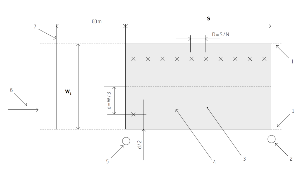
Fig. 1: Calculation field of luminance, positions of calculation points in the lane:
1 – lane edge, 2 – last luminaire in the measuring field, 3 – measuring field, 4 – lane axis, 5 – first luminaire in the measuring field, 6 – direction of observation, 7 – position of luminance meter for longitudinal observation, x – marking of measurement points
The luminance meter should be at a height of 1.5 m above the road level. In the transverse direction, the meter should be positioned successively in the centre of each lane of the road. The average luminance and the overall uniformity of luminance should be measured for the whole roadway and for each position of the meter. From the driver’s point of view the road area between 60 m and 160 m in front of the vehicle is important. With the driver’s level of vision set at a height of 1.5 m above the road surface (or, if measured, from the measuring position), the angle between the optical axis of the measuring device and the road surface changes between 1.5° and 0.5°. Performing measurements in this range requires a precise system which will allow changing the inclination of the meter with high resolution so as to aim the measurement field at the given measurement point located in the distance range described above.
KONZEPT EINES BILDGEBENDEN LEUCHTDICHTEMESSSYSTEMS (ILMD)
The standard recommends that, in order to obtain a correspondence between the measured and calculated values, location of the measurement points and the observer’s position should be the same as the positions used in the calculations. It is recommended that these positions are also in accordance with the requirements of EN 13201-3. The application of such requirements leads to the following problems:
a very large number of measuring points is created,
measurement of luminance distributions becomes a difficult task. Problems that may occur in the luminance measurement are rather related only to the large number of measurement points. On the other hand, the problems occurring during luminance measurements can be presented in the following points:
the need for a precise and technically advanced luminance meter, which should limit the total angle of the measurement cone to 2 arcminutes on the vertical surface and to 20 arcminutes on the horizontal surface,
possibility of overlapping of measuring fields from neighbouring points,
problems with precise targeting of the meter’s observation field on the measurement field.
Fig. 2 shows a perspective view of the road with the density of measurement points further away from the observer.

Fig. 2. Density of measurement points.
The long lasting experience of the Poznan University of Technology team shows that measurements made with a spot luminance meter make it practically impossible to perform a reliable measurement, especially the distribution of luminance, and, thus, to obtain an objective value of luminance uniformity. The above problems can be solved if an Imaging Luminance Measuring Device (ILMD) is used. The operation of such a meter is similar to that of a digital camera. Professional versions of such meters do not have an optical viewfinder, and the analysed image can be displayed on the screen of a portable computer. Measurements are made by means of

Abbildung 2: Perspektivische Darstellung des Messbereichs.
- setting the meter in an appropriate place,
- marking of the measuring field (including its dimensions),
- single recording of the analysed surface image,
- processing of the recorded image outside the place where the measurements were taken.
The team of the Department of Light Technology and Electrothermal Energy of the Poznań University of Technology has many years of experience in performing luminance measurements on roads with the use of both a spot luminance meter and an Imaging Luminance Measuring Device. The use of an ILMD meter makes it much easier to perform measurements and helps to obtain more reliable results allowing for unambiguous assessment of the state of road lighting installation.
The Poznan University of Technology team is in possession of one of the most popular imaging luminance meters. The meter requires connection to a PC on which the software is running. This program can be enriched with an EN13201 Add- On enabling calculation of luminance on the road in accordance with the EN 13201 standard.
After performing a number of measurements with the use of this meter, the Poznań University of Technology team states that the currently available luminance meters are not sufficiently well adapted to perform measurements of luminance distributions on the road.
Meters of this type, produced by different companies, are basically laboratory meters and performing measurements by their means in the field is very cumbersome.
- eine zuverlässige Stromversorgung,
- Tags, die das Markieren des Messfeldes ermöglichen,
- eine an das Messfeld angepasste Optik,
- ein integriertes Modul, welches ein effizientes und schnelles Einstellen des Messsystems in einer bestimmten Position durch eine Person unter Berücksichtigung der Anforderungen der Norm EN 12301 ermöglicht,
- ein komfortables System zum Messen des Abstands zwischen dem Messgerät und dem Anfang des Messfeldes,
- eine benutzerfreundliche Software, die es ermöglicht, Ergebnisse zur Bewertung der Qualität der Straßenbeleuchtung gemäß EN 12301 in Echtzeit zu erhalten.
The project of developing a modern measuring instrument
The GL Optic company with its R&D Center based in Poland, specializing in the production of lighting measurement devices, cooperates with the Poznań University of Technology at the stage of research and development and the industrial research within the project: “Development of a system for Imaging luminance measurement system” which is co-financed by the European Union from the European Regional Development Fund within the Smart Development Programme. The project is implemented within the framework of the National Centre for Research and Development “Fast Track” programme.
The project assumes working on a measurement system that enables measurement of luminance distribution. The result of the work will be the development of a comprehensive system for imaging measurement of luminance with particular emphasis on the measurement of road lighting in accordance with the requirements of EN 13201 and in laboratory applications.
ZUSAMMENFASSUNG
Among the project scope, there will be the development of self-exposure adaptation method. The method will be based on a programme analysing the meter’s view field in real time and eliminating the high level luminance fields (mainly luminaires) from the analysis. It will allow for a precise adjustment of the matrix exposure time to the range of luminance occurring on the measured road surface.
Measurements of the luminance distribution on the road should be made by placing the meter in the centre of the traffic lanes. We may have to deal with a different number of lanes and their different width. One of the tasks of the project will be to develop the optical system of the meter, which will enable measurements to be made with appropriate angular resolution corresponding with the human eye resolution under conditions of adaptation to the luminance levels occurring in a road illuminated by artificial light. According to the authors of the project, their decision to work on the new meter is motivated by the fact that the currently available luminance meters on the market do not take into account the above assumptions.
An important task of the project will be to develop a measuring system consisting not only of an imaging luminance meter, but also of peripheral devices enabling comfortable measurement of luminance distribution on roads, not requiring specialist knowledge. The imaging luminance meters available on the market are expensive, complicated to operate and not fully adapted to perform luminance measurements on roads in accordance with the requirements of EN 12301. The developed system will enable efficient measurements to be performed by operators who do not have academic expertise.
The new system will include:
- a reliable power supply,
- tags enabling the marking of the measurement field,
- optics adapted to the measuring field,
- integrated module enabling efficient and quick setting of the measurement system in a given position by one person, taking into account the requirements of EN 12301,
- convenient system for measuring the distance between the meter and the beginning of the measuring field,
- friendly software enabling efficient, convenient and quick obtaining of results to assess the quality of road lighting according to EN 12301 in real time.
Measurements with the Imaging Luminance Measuring Device – important aspects
In order to correctly measure the distribution of luminance on the road in accordance with the requirements of the standard, the measuring field between two successive luminaires must be selected. The section of the road to be measured should be straight. This is rarely the case in practice. Select a section of the road with as little bands as possible and, when analysing the measurement results, check that the measuring points do not overlap with the road markings, e.g. the lane dividing lines. In addition, the road behind the measuring field should be illuminated at a distance of at least twelve times the height of the lamp post.
The next important step is to mark the measuring field correctly. The markers of the measuring field should clearly indicate the actual boundaries of the area to be measured. This is necessary for the positioning of the calculation points during the analysis of the image recorded with the matrix luminance meter.
The next thing to pay attention to is the position of the meter during the measurements. The meter should be positioned in the centre of each lane at a height of 1.5 m above the road surface and 60 m in front of the measuring field, and the optics used must be such that the luminance can be measured over the entire width of the measured road.
Finally, before the measurement is taken, the appropriate exposure time must be chosen according to the luminance level of the measuring field.
Summary
Verification of the project brief consisting in the assessment of lighting parameters on the road is possible thanks to the use of high-class meters adapted for these purposes. The choice of the meter is particularly important for luminance measurements, as these measurements are difficult, time-consuming and require traffic stops during preparation and measurement. In this situation, the best solution is to use for measurements a measurement system consisting of an imaging luminance meter with appropriately selected optics and user-friendly software, evaluating the parameters on the road in accordance with the requirements of the EN 13201:2016 standard.
Efficient execution of the measurements will be possible if the system is equipped with additional elements, such as: tags for marking the measurement field, a device for measuring the distance between the meter and the measurement field, an integrated module for setting the meter at the appropriate height and position with a computer. The compact form of the measuring system will enable fast and efficient measurement of the luminance distribution on the road by one person only and will minimize the nuisance associated with the reduction of vehicle traffic during measurements, if the measurements are made on the roads in operation.
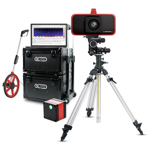
Imaging Luminance Measuring Device
GL OPTICAM 3.0 4K TEC – innovative tool for Road Lighting Luminance Measurements
Imaging Luminance Measuring Device with optics for a wide range of applications: general lighting measurements including LED lamps and luminaires, LED chips and modules, internal and external lighting audits as well as road lighting audits.
- Calibrated and equipped with V-Lambda Correction Filter and CMOS Sensitive Image Sensor.
- It captures images and quickly calculates luminance at every point in the image, all in a single frame and in a single measurement.
- Analytical software provides a user-friendly, intuitive interface for processing recorded data and creating measurement reports.
- Can be connected to the spectrometer allowing for the collection of spectral, colorimetric and luminance data simultaneously.